I admit it: I like Startrek. This is why I called a special pattern used to adopt editors for using them in a 3D scene with
GEF3D "Borg-Factory-Pattern" (a borg factory modifies an object after it has been created by a "normal" factory using assimilators). Kristian Duske recently "3d-fied" the
Ecore Diagram Editor---but he did not use the borg factory. So, why didn't we need the borg technology to assimilate this editor to be used in a 3D scene? The Ecore Diagram Editor is based on
GMF. Frankly, I have lots of respect for GMF. I know
GEF pretty well, but GMF with its thousands of new extension points, policies and stuff... it's like... like.. yeah, it's like a Borg cube. The good thing about that is that borg technology is already on board. We beamed Kristian on board of that cube, and he returned with a some nice providers enabling us to add 3D-behaviour to existing GMF editors. GEF3D needed some more examples anyway, so we 3d-fied the Ecore editor, and some of the UML editors of the
UML Tools (which are also GMF-based), viz. the class, activity, and use case editors. The best thing: We only had to write a bunch of classes. For example, the 3D UML class editor plugin consists of 8 classes with only 212 statements (measured by
c_count).
The 3D versions of these editors are available from
GEF3D's SVN repository (plugins org.eclipse.gefd.examples.uml and org.eclipse.gefd.examples.ecore). To give you an impression about what you need to 3d-fy an existing 3D GMF-based editor, here is a brief description on how we adopted the UML class editor (a tutorial about GEF3D is planned for June, since then don't hesitate to post your questions in the GEF3D newsgroup!):
- First, a new plugin is created, with a
UMLDiagram3DPlugin activator, which is not really needed.
- A new editor class
UMLDiagramEditor3D subclasses the original UMLDiagramEditor. Instead of a 2D viewer we have to instantiate a 3D viewer, actually, this need the most code since we have to copy and paste some code from the base classes.
- Only one editpart and figure have to be exchanged, that is the pair for the diagram, here the package. We have to provide new 3D versions for these two classes (
PackageEditPart3D, DiagramFigure3D).
- The new edit part has to be created by a new factory
UMLEditPartFactory3D, which subclasses the original UMLEditPartFactory
- This factory has to be injected into the editor somehow. This is done using a GMF provider
UMLEditPartProvider3D. Since we only need this provider for our 3D editor, we have added a very dirty hack to identify which editor calls the provider. This is hack is really dirty (better not look at the provider ;-) ), and I hope to find a better solution.
- Finally we have to exchange the policy which creates the 2D feedback handles and replace it with a 3D version. Again, this is done by a provider called
UMLEditPolicyProvider3D, the 3D policy is called Handles3DEditPolicy
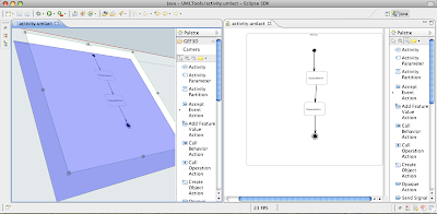
That's it. And what do you get for that? The result is an UML editor with the diagram projected on a plane in a 3D scene. You can use the camera to orbit and move around. Since it's derived from the original 2D UML editor, it is (more ore less) fully editable. Try to select classes and move them around, create new classes and so on. You can even open the very same UML model in the 3D editor and 2D editor simultaneously, changes are reflected in both editors automatically!
 The 3D version of the UML Tool's activity diagram editor (on the right hand side, 2D version on the left). Note the 3D handles and the transparent feedback figure!
Unfortunately there are some open issues which restrict the 3D editor: no edges can be drawn (sometimes, you can draw edges but don't see any feedback, sometimes the Eclipse IDE crashes when you try to do that). You cannot open more then one 3D editor at a time, we have a problem with the texture manager. And there are
some other bugs... So many bugs? Yes, but only a very few lines of code to 3d-fy an editor. So, 3D-fy your editor and help us fixing the bugs!
You may ask, huh, that's great, but why should I want to 3d-fy my editor? Well, I can think of many use cases: display multiple diagrams within one 3D scene and draw inter-diagram connections, annotate your diagrams with 3D elements (e.g. metrics drawn as 3D bars on top of classes), exchange some of your 2D figures and provide real 3D editors...

